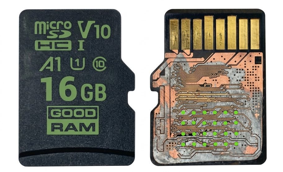
An FPV drone equipped with a compact video camera crashed. The SD card inserted in the camera, which was used to record video, was damaged. Accessing the data through the SD interface was no longer possible, leaving direct NAND interface reading as the only remaining option. The memory chip features a standard 4 × 6 contact layout.
| Manufacturer | Goodram |
|---|---|
| Controller | Phison |
| Chip ID | 983A98A376 |
| Chip count | 1 |
| Page structure | 1×(1024 Data + 9 SA + 105 ECC) + 15×(1024 Data + 5 SA + 105 ECC) |
| ECC | BCH |
| XOR | Data only |
XOR key
The NAND data was analyzed using two separate reads, acquired in SLC (Single-Level Cell) and TLC (Triple-Level Cell) modes. These modes differ in how information is stored in memory cells, which also affects the XOR descrambling process.
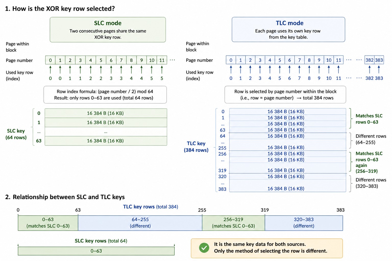
The XOR key consists of 384 rows, each containing 16,384 bytes. The XOR operation is applied only to the data area, leaving the spare area (SA) and error-correction data (ECC) unaffected. In SLC mode, every pair of pages uses the same XOR key row.
The XOR key was derived by analyzing the raw NAND reads. Repeated 1 KB sectors were compared, and the most frequently occurring value for each sector was determined using a majority-voting method. At least 79 identical copies were found for each sector.
Since the corresponding original data values were zeros, comparing the repeated copies made it possible to determine the XOR key values.
The XOR key row selection scheme and the correspondence between the SLC and TLC keys are illustrated in the infographic in Figure 1.
Logical Mapping
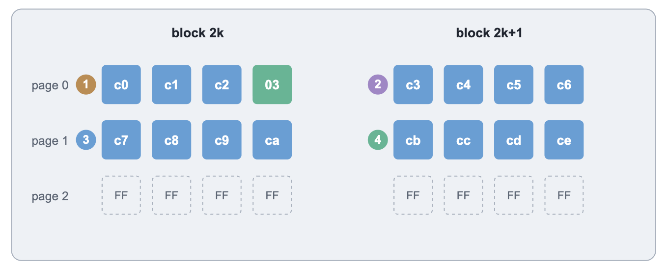
The controller uses two consecutive physical blocks, 2k and 2k+1, to construct each logical page. Four 4 KB data units are read from each block, resulting in a total of eight units, or 32 KB per logical page.
Each 4 KB data unit contains its corresponding Logical Block Number (LBN) in the spare area (SA). This makes it possible to reconstruct the logical image by sorting all data units according to their LBN values.
In most cases, the LBN values form a sequential sequence. However, there are also exceptions that must be taken into account during the data mapping process (see Figure 2).
LBN Calculation and Data Offset
The Logical Block Number (LBN) is calculated by combining three byte values from the spare area (SA):
LBN = (SA1[0] << 16) | (SA0[1] << 8) | SA0[0]
The << operator represents a bitwise left shift, while | represents the bitwise OR operation. This combines the three byte values into a single 24-bit number.
For example:
SA1[0] = 0x12  →  0x120000 // Shifted left by 16 bits
SA0[1] = 0x34  →  0x003400 // Shifted left by 8 bits
SA0[0] = 0x56  →  0x000056 // Remains in its original position
--------
LBN = 0x123456
Once the LBN is calculated, you can determine the corresponding data unit's location in the logical image. Since each mapping unit is 4 KB, or 4096 bytes, its starting offset is calculated as follows:
Offset = LBN x 4096For example:
0x123456 × 4096 = 0x123456000The resulting value specifies the starting byte offset of the corresponding 4 KB data unit, measured from the beginning of the logical image.
Distinguishing User Data from System Metadata
User data units (TLC) are distinguished from system tables stored in SLC mode by a two-byte header value of 0xFF00.
A total of 219 blocks were written in SLC mode. Their contents are taken from the SLC read, while the corresponding data copies are excluded from the TLC read to avoid duplicating the same content.
The following check is used to identify these blocks:
SA0[3] ‖ SA1[1] = 0xFF00
The ‖ operator denotes the concatenation of two byte values in the specified order, producing a 16-bit value.
File System Location
In the reconstructed logical image, the FAT32 file system's boot sector is located at LBN 0x400, corresponding to LBA 8192 and the following byte offset:
0x400 × 4096 = 4 194 304 bytes
This places the boot sector 4 MiB from the beginning of the image. This is consistent with the assumption that the partition starts at LBA 8192.
Logical Disk Image Reconstruction
Scanning approximately 27 GB of raw NAND data yielded around 3.80 million unique LBN records.
Approximately 88,000 LBNs have multiple data copies. Therefore, the main challenge is no longer locating the data or determining its logical order, but selecting the correct copy of each data block.
To reconstruct the file system as accurately as possible, the available copies must be compared using metadata and write-order indicators. This analysis led to the implementation of multiple translator revisions, allowing different logical disk images to be generated using different data block selection strategies.
Result
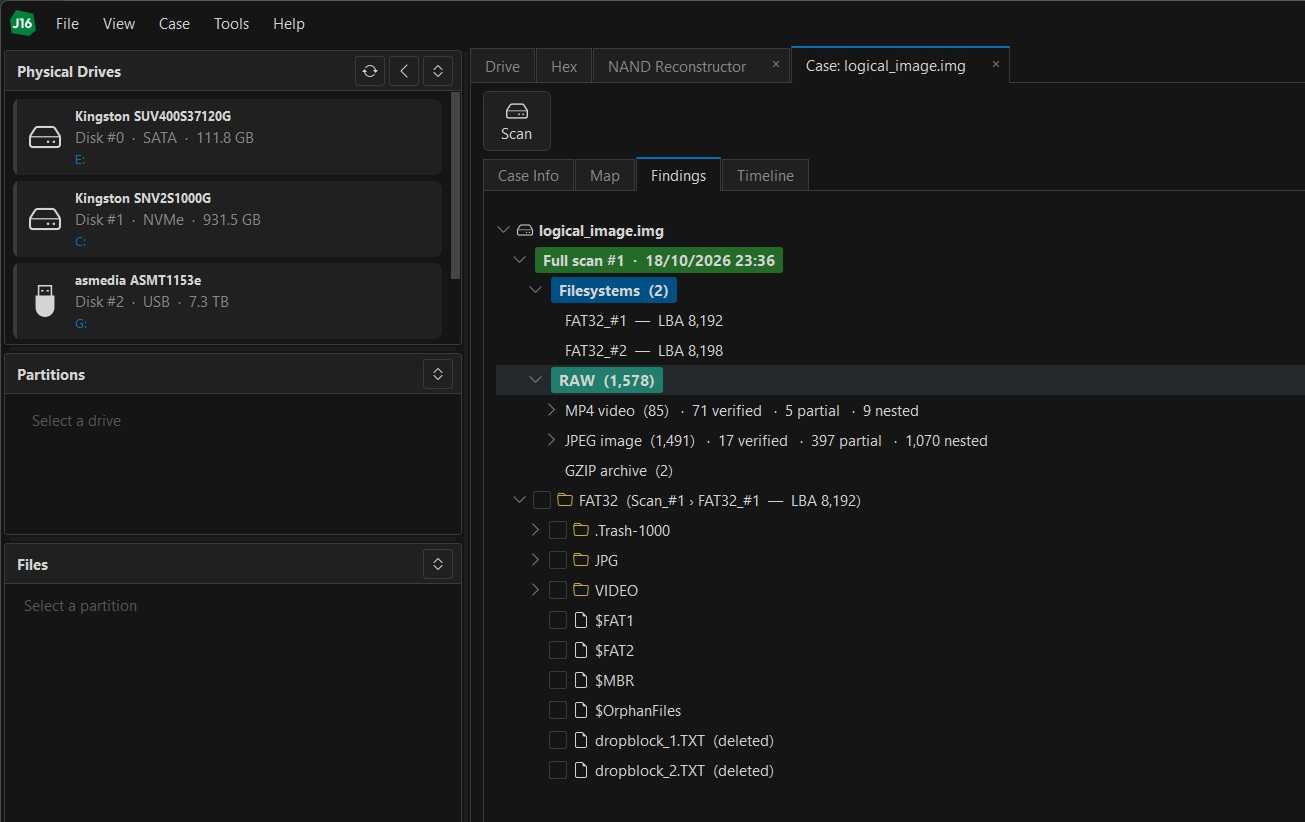
The file system was successfully reconstructed, along with the drone's flight video recordings.